Plans and Elevations of 3D Shapes
Updated July 2026
This topic covers how to interpret and draw two dimensional representations of three dimensional objects. You will learn to identify plans, front elevations, and side elevations, which are vital for visualising complex solids in the ESAT Mathematics 1 paper. These projections provide a precise method for describing an object's geometry from multiple perspectives.
A plan is the view from directly above a shape, while the front and side elevations are views from the front and side respectively. Together, these three orthographic projections provide the necessary information to reconstruct the three dimensional dimensions of a solid.
What are Plans and Elevations?
Representing a three dimensional solid on a two dimensional surface requires different perspectives known as projections. The most common projections are the plan, the front elevation, and the side elevation.
The plan of a three dimensional shape is the view obtained when looking directly down onto the object from above. This view shows the footprint of the object and the layout of its features as they would appear on the ground.
For example, the plan of a square based right pyramid displays the square base and the lines representing the edges leading to the apex, which appears as a central point where the diagonals meet:
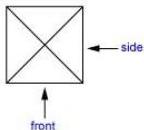
When constructing these diagrams, it is standard practice to label the 'front' and 'side' directions on the plan to maintain consistency across all views. While a plan provides the layout of the shape, it does not provide information regarding the height of the object or whether specific parts are stacked on top of others.
Understanding Elevations
To understand the height and vertical profile of an object, we use elevations:
- The front elevation is the view seen when standing directly in front of the object. The problem will usually specify which direction is considered the 'front'.
- The side elevation is the view seen when looking directly at the side of the object.
In the case of the square based right pyramid mentioned earlier, both the front and side elevations are identical. They appear as triangles where the base of the triangle is equal to the length of the pyramid's base, and the height of the triangle is equal to the vertical height of the pyramid.

Drawing Plans and Elevations of Common Solids
When drawing projections for curved solids like cylinders and cones, the resulting 2D shapes may look simpler than the 3D objects they represent.
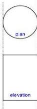
The Cylinder The plan of a cylinder is a circle. The side elevation of a cylinder, regardless of the angle from which it is viewed, is a rectangle. The width of this rectangle is equal to the diameter of the cylinder's base, and its height is equal to the height of the cylinder.
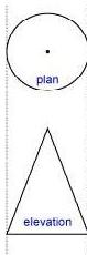
The Cone The plan of a cone is also a circle, but it must include a central dot to represent the vertex (the tip) of the cone. The side elevation of a cone is an isosceles triangle. The base of this triangle is equal to the diameter of the cone's base, and the height is equal to the vertical height of the cone.
Note that in these drawings, dotted lines are often used for alignment during construction but are not strictly part of the final answer. Additionally, side elevations do not show the curved lines of the bases; they are represented as straight lines.
Constructing a Solid from Projections
If you are given the plan, front elevation, and side elevation, you can reconstruct a possible three dimensional solid, often using isometric paper. Consider the following set of views:
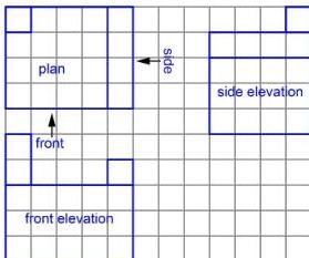
The plan indicates a large rectangle measuring squares by squares, containing two smaller rectangular features. The elevations suggest a base that is units high. While multiple solids could potentially fit these views, we can construct one logical solution.
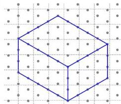
First, we draw the main rectangular base. Based on the elevations, it is units long, units wide, and units high:
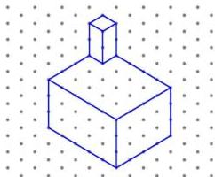
Next, the plan shows a single square cross section located at the back right hand corner of the base. Looking at the front elevation, we can see this specific part is cubes high above the base:
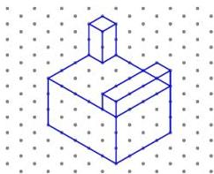
Finally, the plan shows another rectangular block along the side edge. Both the front and side elevations indicate that this block is cube high. Adding this to our isometric drawing gives us the final possible solid:
Key takeaways
- A plan is the view from the top, while front and side elevations are views from the respective sides.
- The plan of a cone must include a central dot to indicate the vertex.
- Elevations of curved surfaces like cylinders and cones are drawn as flat 2D polygons, such as rectangles or triangles.
- To reconstruct a 3D solid, you must synthesise information about length and width from the plan and height from the elevations.
Always use a ruler to ensure that the widths in your plan align perfectly with the widths in your front elevation. Consistency between the diagrams is key to a correct interpretation.
Do not confuse the slant height of a cone or pyramid with the vertical height used in the elevations. The height of the triangle in an elevation must represent the perpendicular vertical height of the solid.
This method of representation is known as orthographic projection. It is a fundamental tool in engineering and architecture because it allows three dimensional objects to be described precisely without the distortion found in perspective drawings.
Frequently asked questions
Does a plan always show the base of the object?
A plan shows the view from above looking down. While it often reflects the footprint of the base, it actually shows the top most surfaces and the outermost boundaries of the object.
What is the difference between a side elevation and a front elevation?
The front elevation is the view from a specified 'front' direction, whereas the side elevation is the view from a direction at a degree angle to the front. They provide different vertical profiles of the same object.
Why do the elevations of a cylinder look like rectangles?
Elevations are orthographic projections, meaning every point is projected perpendicularly onto a flat plane. Because all points on the side of a cylinder are at the same distance from the centre, they project into a flat rectangular area.
Are hidden lines always required in these drawings?
In many basic interpretations, only visible edges are drawn. However, in more advanced technical drawings, hidden edges may be shown with dashed lines to provide more detail about the internal structure.