Electric Circuits and Components for the ESAT
Updated July 2026
This guide covers the fundamental principles of electric circuits required for the ESAT. It explains how to identify circuit symbols, distinguish between alternating and direct current, and apply the relationships between charge, current, voltage, and resistance. You will also learn to analyze component characteristics and calculate power and energy transfer.
Electric circuits are loops that facilitate energy transfer from a supply to a load. Current is the rate of flow of charge (), while voltage represents the energy transferred per unit charge (). These are linked by resistance () and are governed by specific rules for series and parallel configurations.
Circuit Symbols and Diagrams
Components in electrical circuits are represented by standard symbols to ensure clarity and consistency. You must be able to recognise and draw these for the ESAT.


The standard symbols include:
- Wire crossing (not connected): Two wires passing over each other without contact.
- Wires connected: A dot or junction showing an electrical connection.
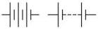
- Cell: A single unit providing potential difference.
- Battery: A group of cells or a dc power supply.
- AC Power Supply: Represented by a circle with a wave inside.
- Switch: Always shown in the open or off position in standard diagrams.
- Fixed Resistor: A component that resists the flow of current.
- Variable Resistor: A resistor whose resistance can be adjusted.
- Ammeter: A device to measure current.
- Voltmeter: A device to measure potential difference.
- Light Source: A filament lamp.

Specialised components include:
- Thermistor: A temperature-dependent resistor.
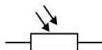
- Light Dependent Resistor (LDR): A light-dependent resistor.
- Diode: A component allowing current in only one direction.

Series and Parallel Connections
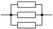
Components can be connected in two main ways: in a single loop (series) or in multiple branches (parallel).
Alternating and Direct Current
There are two types of electrical current based on the direction of charge flow:
- Direct Current (dc): The current flows continuously in the same direction. Cells and batteries are sources of dc.
- Alternating Current (ac): The current repeatedly changes direction, usually very rapidly. Generators in power stations produce ac. In the UK, the mains supply frequency is 50 Hz, meaning the current changes direction 100 times per second, completing 50 full cycles.
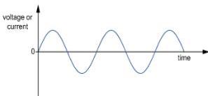
Waveforms are used to visualise these currents on an oscilloscope. A common ac waveform is the sine wave, where positive values represent current in one direction and negative values represent the opposite direction.
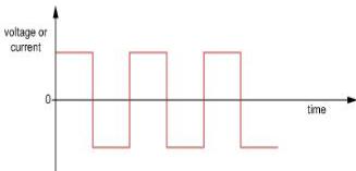
Another example is the square wave, where the voltage switches sharply between positive and negative.
Worked Example: Identifying ac
Consider the following three waveforms:
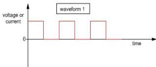
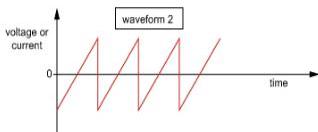
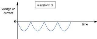
Which of these represents alternating current? Only waveform 2 is ac. A current is only alternating if its waveform includes a line that is sometimes above and sometimes below the axis, indicating a change in direction.
Conductors and Insulators
Materials are classified by how easily they allow charge to flow:
- Conductors: Materials with very low resistance. Examples include all metals (especially copper, gold, and silver), graphite (carbon), and ionic solutions.
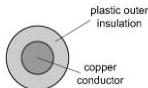
- Insulators: Materials with very high resistance. Examples include most non-metals, plastics, rubber, dry wood, air, and a vacuum.
Water is generally a conductor unless extremely pure. This is why wet materials are poor insulators. For safety, bathroom lights use nylon pull-cords. Because water can condense on surfaces in a steamy bathroom, a standard switch might conduct electricity to a person's hand through the moisture. Nylon is an insulator and does not absorb water, preventing electric shocks.
Current and Charge
Electric current is defined as the rate of flow of electric charge . It is measured in amperes (A), where .
The formula is:
In metals, current is the flow of free electrons. While conventional current flows from the positive terminal to the negative terminal, the actual electrons move from negative to positive.
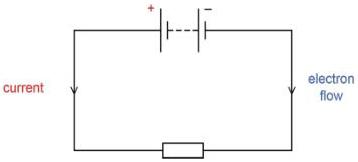
In liquids (electrolytes), conduction involves the movement of ions. Positive ions move toward the negative cathode, while negative ions move toward the positive anode.
Worked Example: Charge Calculation
A current of 30 mA exists in a resistor for 20 s. How much charge passes through? Using : .
Worked Example: Average Current
A charge of passes through a component in 50 minutes. Find the average current. .
Use of Voltmeters and Ammeters
To measure circuit properties correctly:
- Ammeters must be connected in series with the component. They have very low resistance to avoid reducing the current they measure.
- Voltmeters must be connected in parallel with the component. They have very high resistance to avoid short-circuiting the component by drawing current away from it.
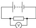
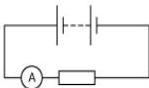
Worked Example: Identifying Meters
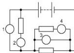
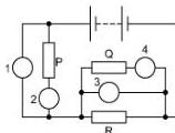
In the circuit above:
- Meter 1 is a voltmeter (parallel to P).
- Meter 2 is an ammeter (series with P).
- Meter 3 is a voltmeter (parallel to R).
- Meter 4 is an ammeter (series with Q).
Resistance and Ohm's Law
Resistance is defined by the ratio of voltage to current :
For an ohmic conductor at a constant temperature, current is directly proportional to voltage (). This is known as Ohm's law. Resistance is measured in ohms ().
Worked Example: Finding Resistance
A resistor has a current of 60 mA when connected to a 12 V battery. .
V-I Characteristic Graphs
Fixed Resistors
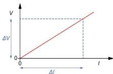
A fixed resistor at constant temperature obeys Ohm's law. A graph for a fixed resistor is a straight line passing through the origin. The resistance is determined by the gradient .
Filament Lamps
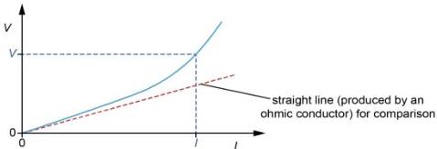
A filament lamp does not have constant resistance. As current increases, the filament becomes hotter, which increases its resistance. The graph is a curve. At any specific point, resistance is still , but it is not equal to the gradient of the curve.
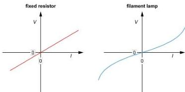
Both components behave the same regardless of current direction. Full graphs showing negative values look like this:
Thermistors, LDRs, and Diodes
- NTC Thermistor: A negative temperature coefficient thermistor. As temperature increases, its resistance decreases.
- LDR: A light-dependent resistor. As light intensity increases, its resistance decreases.
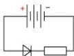
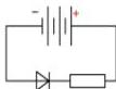
- Ideal Diode: A component that only allows current in the direction of the arrowhead in its symbol. Current flows if it is forward biased (arrow pointing from positive to negative) and is blocked if reverse biased.
Worked Example: Thermistor Circuit
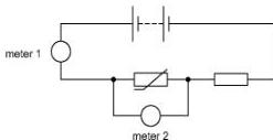
If the temperature of an NTC thermistor decreases, its resistance increases. This raises the total circuit resistance and decreases the current (Meter 1 reading drops). Since and the current has decreased, the voltage across the fixed resistor drops. This causes the voltage across the thermistor (Meter 2) to increase, as it now takes a larger share of the fixed supply voltage.
Worked Example: Diode Logic
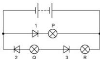
Which lamps are lit? Lamp P is not lit because Diode 1 is reverse biased. Lamps Q and R are not lit because Diode 3 is reverse biased, blocking current for that entire series branch.
Rules for Series and Parallel Circuits
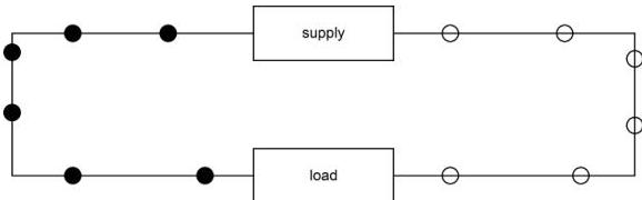
In a simple circuit, charge carries energy from the supply to the load.
Series Circuits
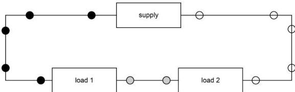
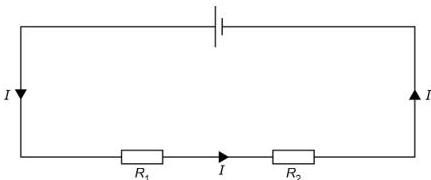
- The current is the same at all points.
- The supply voltage is shared between components: .
Parallel Circuits
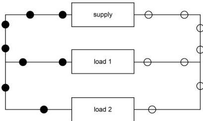
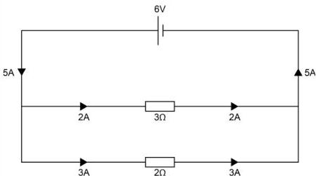
- The voltage across each branch is the same.
- The total current into a junction equals the total current leaving it: .
Calculating Resistance
- Series Resistance: The combined resistance is the sum of individual resistances: . Combined resistance is always greater than any individual resistor.
- Parallel Resistance: The combined resistance is always less than the resistance of any individual resistor in the parallel combination. For example, two resistors in parallel have a combined resistance of .
Power and Energy Transfer
Voltage is energy per unit charge (). Electrical power (the rate of energy transfer) is calculated using:
Units: .
Energy transfer over time is given by:
Final Complex Example:
Two resistors, and , are in parallel. This group is in series with a resistor connected to an 18 V supply. The resistor dissipates 36 W. Calculate the energy dissipated in the resistor in 1 minute.
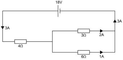
- Find current in the resistor: .
- The current splits at the junction. Since the resistor has half the resistance of the resistor, it takes twice the current. Thus, goes through the and goes through the .
- Voltage across the resistor: .
- Energy dissipated: .
Key takeaways
- Current () is measured in Amperes; Voltage () is measured in Volts.
- Ohm's Law states for ohmic conductors; filament lamps are non-ohmic as resistance increases with heat.
- In series, current is constant and voltages add up; in parallel, voltage is constant and currents add up.
- The total resistance of a parallel combination is always less than the resistance of any individual component in that combination.
- Electrical power is the rate of energy transfer: .
When solving circuit problems, always check units first. ESAT questions often mix mA or microA with Volts. Convert everything to SI base units (Amperes, Ohms, Volts, Joules, Seconds) before using formulas like or .
A common mistake is assuming the gradient of a filament lamp's graph is the resistance. For non-linear components, the resistance at a point is simply the value of divided by the value of at that specific point, not the slope of the curve.
The rules for current and voltage are actually applications of fundamental conservation laws. The current rule for parallel junctions is a statement of the Conservation of Charge, while the voltage rule for loops is a statement of the Conservation of Energy.
Frequently asked questions
Why does a voltmeter need to have a very high resistance?
A voltmeter is connected in parallel. If it had low resistance, it would provide an easy path for current to flow through it rather than the component being measured, effectively short-circuiting the component and changing the circuit's behaviour.
How do you distinguish between ac and dc on a waveform graph?
Direct current (dc) is represented by a line that stays on one side of the horizontal axis. Alternating current (ac) must cross the axis, with the graph line appearing both above (positive) and below (negative) the axis.
What is the difference between conventional current and electron flow?
Conventional current is the historical convention that charge flows from the positive terminal to the negative terminal. However, in metallic conductors, it is actually negatively charged electrons that flow from the negative terminal to the positive terminal.
Does the resistance of an LDR increase or decrease in the dark?
The resistance of a Light Dependent Resistor (LDR) increases in the dark. As the light intensity increases, the resistance decreases.