Transformers and Power Transmission for the ESAT
Updated July 2026
Transformers are essential electrical components that use electromagnetic induction to change the voltage of an alternating current supply. They play a critical role in the national grid by stepping up voltages for efficient long distance transmission and stepping them down for safe domestic use. Understanding the relationships between voltage, current, and turns is vital for the ESAT.
A transformer changes alternating voltages by using a changing magnetic field in a primary coil to induce an alternating voltage in a secondary coil, governed by the ratio of turns: .
Understanding Step-up and Step-down Transformers
Transformers are devices that utilise electromagnetic induction to change the voltage of an alternating current (ac) supply. They are categorised into two main types based on their function:
- A step-up transformer increases the voltage from the input to the output.
- A step-down transformer decreases the voltage from the input to the output.
Physically, a transformer consists of two separate coils of wire wound around a common soft iron core. The input side is referred to as the primary coil, while the output side is known as the secondary coil.
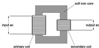
These devices are ubiquitous in modern life. Step-down transformers are used to reduce the 230 V mains supply to the lower voltages required by laptops and phone chargers. Conversely, step-up transformers are used at power stations to increase the voltage for long distance transmission across the country.
Why Transformers Require Alternating Current
For a transformer to function, there must be a change in the magnetic environment. When an alternating current flows through the primary coil, it generates a magnetic field in the iron core that passes through the secondary coil. Because the ac current is continuously changing, the magnetic field it produces is also continuously changing. This changing magnetic field induces a continually changing (ac) voltage in the secondary coil.
The process follows this logical sequence:
Current in primary coil changes → Magnetic field in core changes → Voltage is induced in the secondary coil.
If the primary coil were connected to a direct current (dc) supply, a magnetic field would still be created and pass through the secondary coil. However, because the field would be constant, no voltage would be induced in the secondary coil. Electromagnetic induction requires a rate of change of magnetic flux.
The Role of the Soft Iron Core
The core is made of iron because iron is a magnetically soft material. This means it can be magnetised and demagnetised very quickly, allowing the magnetic field to keep pace with the rapidly changing ac current. The core serves to link the two coils magnetically, ensuring that the magnetic field generated by the primary coil effectively passes through the secondary coil.
Worked Example: Identifying Transformer Characteristics
Which of the following statements about a step-up transformer is or are correct?
- A step-up transformer has more turns on the secondary coil than on the primary coil.
- A step-up transformer is used to increase current.
- A step-up transformer is used to increase the voltage of a dc supply.
- A step-up transformer is used to increase the energy of an ac supply.
Solution:
- Statement 1 is correct. Since the secondary voltage must be higher than the primary voltage, the secondary coil must have a greater number of turns.
- Statement 2 is incorrect. To conserve energy, if the voltage is increased, the current must decrease.
- Statement 3 is incorrect. Transformers require a changing magnetic field and therefore only work with ac, not dc.
- Statement 4 is incorrect. Energy cannot be created. A transformer can change the potential difference but cannot increase the total energy.
The Transformer Equation
In an ideal transformer, which is 100% efficient, the ratio of the voltages across the coils is exactly equal to the ratio of the number of turns on those coils. This is expressed as:
Where:
- is the ac voltage across the primary coil.
- is the ac voltage across the secondary coil.
- is the number of turns on the primary coil.
- is the number of turns on the secondary coil.
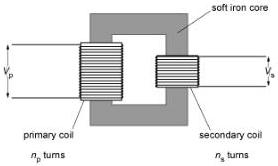
From this relationship, we can see that:
- In a step-up transformer, , which results in .
- In a step-down transformer, , which results in .
While this equation applies strictly to ideal transformers, many real world transformers are efficient enough that the equation remains a highly accurate tool for calculations.
Conservation of Energy and Power
Although a transformer can increase voltage, it does not violate the law of conservation of energy. As the voltage is stepped up, the current in the secondary coil decreases. Since electrical energy transferred is given by , the reduction in current perfectly balances the increase in voltage.
Worked Example: Calculating Turns Ratio
A transformer is used to step down 240 V ac to 20 V ac. Which of the following could be the number of turns on the primary and secondary coils?
a) Primary: 4800, Secondary: 400 b) Primary: 400, Secondary: 4800 c) Primary: 48000, Secondary: 400 d) Primary: 400, Secondary: 48000
Solution: This is a step-down transformer, so must be smaller than . The voltage is reduced by a factor of . Therefore, the ratio of turns must also be 1 to 12. In option (a), , which matches the required ratio. Thus, (a) is the correct answer.
Electrical Power Transfer
An ideal transformer is 100% efficient, meaning the power input to the primary coil () is equal to the power output from the secondary coil ().
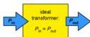
Using the power equation , we can state:
Where and are the currents in the primary and secondary coils respectively. Rearranging this gives the current ratio:
This shows that the current ratio is the inverse of the voltage ratio. If a transformer steps up the voltage by a factor of ten, it steps down the current by a factor of ten. Combining these relationships:
Note: We always name a transformer based on its effect on voltage, not current.
Real Transformers and Efficiency
In reality, no transformer is 100% efficient. Energy is lost as heat due to:
- Resistance in the copper wire of the coils.
- Heating of the core as it is magnetised and demagnetised.
- Eddy currents, which are small currents induced in the core itself by the changing magnetic field.
Worked Example: Current in a Step-up Transformer
A transformer steps up voltage from 25,000 V to 250,000 V. The input current is 4.0 A. What is the output current, assuming 100% efficiency?
Solution: Since : . The voltage increased by a factor of 10, so the current decreased by a factor of 10.
Power Transmission and Grid Efficiency
Electricity is transmitted over long distances through transmission lines. High voltages are used to minimise energy losses. The power being transmitted is . The same amount of power can be sent using a high current and low voltage or a low current and high voltage.
Transmission lines have resistance (). The power wasted as heat in these lines is calculated using:
To reduce wasted energy, the current must be kept as low as possible. This is achieved by using step-up transformers to increase the voltage to very high levels (e.g. 400,000 V) before transmission.
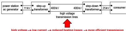
Voltage between cables vs Voltage along cables
It is important to distinguish between two different voltages:
- The voltage between the cables: This is the potential difference between the terminals, which is stepped up or down by transformers.
- The voltage drop along the cables (): This is the potential difference caused by the resistance of the wires themselves. High voltage transmission reduces , which in turn reduces and power loss.
Typical Voltages and Safety
In the UK, typical values include:
- Power station output: 11 kV to 33 kV.
- Long distance transmission: 275 kV to 400 kV.
- Consumer use: 230 V (domestic) or 25 kV (railways).
High voltages are difficult to insulate, making them dangerous for direct consumer use. Therefore, step-down transformers are necessary at the consumer end of the grid.
Worked Example: High Voltage Transmission Logic
Which of the following statements regarding high voltage ac transmission are correct?
- It reduces the current in transmission lines.
- It increases the efficiency of the process.
- It reduces energy losses due to heat.
- It makes it easier to insulate the lines.
- It allows more generated power to reach the consumer.
Solution: Statements 1, 2, 3, and 5 are correct. Higher voltage leads to lower current, which reduces heat losses, making the process more efficient and ensuring more power reaches the destination. Statement 4 is incorrect because higher voltages are actually much harder to insulate.
Key takeaways
- A transformer uses a changing magnetic field to induce a voltage, meaning it only works with alternating current (ac).
- The relationship between primary and secondary voltage and turns is given by .
- In an ideal (100% efficient) transformer, the power input equals power output, so .
- Long distance power transmission uses high voltages to minimise current, which reduces energy lost as heat () in the cables.
- Real transformers lose energy through wire resistance, core heating, and induced eddy currents in the core.
When solving transformer problems, always check if the transformer is step-up or step-down first. This provides a 'sanity check' for your calculations: if it is step-up, your secondary voltage must be higher than the primary.
Do not confuse the voltage between the transmission cables with the voltage drop along the cable. The power loss depends on the current and the resistance of the cable itself (), not the transmission voltage directly.
The use of ac for the national grid was largely decided by the ease with which ac voltages can be transformed. Because we can easily step up ac for efficient transmission and step it down for use, ac became the global standard for power distribution.
Frequently asked questions
Why can't a transformer work with a battery?
A battery provides direct current (dc), which creates a constant magnetic field. Since electromagnetic induction requires a changing magnetic field to induce a voltage in the secondary coil, a dc source will not produce an output voltage.
How does the iron core help the transformer?
The soft iron core is easily magnetised and demagnetised. It provides a path that guides and concentrates the magnetic field lines from the primary coil through the secondary coil, ensuring efficient magnetic coupling.
What is the difference between an ideal and a real transformer?
An ideal transformer is 100% efficient with no energy loss. A real transformer loses energy as heat due to the electrical resistance of the coils and magnetic effects within the iron core.
Why is the voltage stepped down before it enters a home?
The very high voltages used for transmission (up to 400,000 V) are extremely dangerous and difficult to insulate in domestic settings. Domestic appliances are designed to operate safely at much lower voltages, typically 230 V.