The Motor Effect and DC Motors
Updated July 2026
The motor effect describes the force exerted on a current-carrying conductor when it is placed within an external magnetic field. This interaction is fundamental to the operation of electric motors, loudspeakers, and various industrial applications. You must understand how to determine force direction using Fleming's left-hand rule and calculate magnitude using .
A conductor carrying an electric current in a magnetic field experiences a force, provided the current is not parallel to the field lines. This motor effect arises from the interaction between the magnetic field of the current and the external magnetic field, producing a force perpendicular to both.
The Motor Effect
When a wire carrying an electric current is placed within a magnetic field so that it crosses the magnetic field lines, it experiences a physical force. This phenomenon is known as the motor effect. This effect can be demonstrated by placing a straight wire between the poles of a permanent magnet. When the current is switched on, the wire is physically displaced or pushed out of the field.
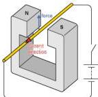
It is vital to note that the force does not pull the wire directly toward or push it away from the magnetic poles. Instead, the force acts in a direction that is perpendicular to both the direction of the current and the direction of the magnetic field. If the current flows parallel to the magnetic field lines, no motor effect force is produced. The force reaches its maximum value when the current and magnetic field are at right angles (90 degrees) to each other.
The Origin of the Motor Effect Force
All electric currents generate their own magnetic fields. When a current-carrying wire is placed in an external magnetic field, such as one created by permanent magnets, the two fields interact. This interaction results in a resultant force on both the wire and the magnets.
Consider the following three scenarios: (i) a uniform horizontal field between two magnets, (ii) the circular field around a wire carrying current into the page, and (iii) the combined field when the wire is placed between the magnets.
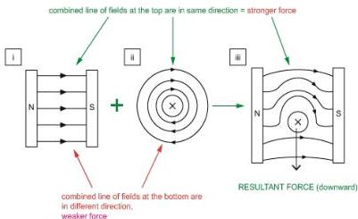
In the combined field, the magnetic field lines are more concentrated (stronger) on one side of the wire and less concentrated (weaker) on the other. The wire experiences a force directed from the region of stronger field toward the region of weaker field. One can imagine the magnetic field lines acting like stretched elastic threads that exert a force as they try to contract. According to Newton's third law, if the wire experiences a downward force, the permanent magnets experience an equal and opposite upward force.
Moving Charges
Since an electric current is defined as the flow of charge, a beam of charged particles (or even a single moving charged particle) also constitutes a current. Consequently, the motor effect force acts on moving charges in a magnetic field, which can be used to deflect their paths.
Determining Direction: Fleming's Left-Hand Rule
The direction of the motor effect force is always mutually perpendicular to the current and the magnetic field. To predict this direction, we use Fleming's left-hand rule.
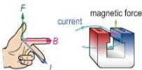
To apply the rule, hold your left hand so that the thumb, first finger, and second finger are all at right angles to each other:
- The First Finger points in the direction of the magnetic Field (from North to South).
- The Second Finger points in the direction of the conventional Current (from positive to negative).
- The Thumb then points in the direction of the Motor effect force (the resulting motion).
Reversing either the current or the magnetic field will reverse the direction of the force. If both are reversed simultaneously, the direction of the force remains unchanged.
Using Components for Directions
When using the left-hand rule, the first finger must represent the component of the magnetic field that is perpendicular to the current. If the field and current are not at 90 degrees, only the perpendicular part of the field contributes to the force.

If the current is parallel to the magnetic field, there is no perpendicular component, and therefore the force is zero. Charged particles moving parallel to field lines experience no deflection.
Worked Example: Identifying Forces on a Circuit
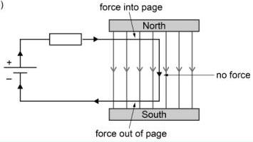
Consider a circuit where part of the wire passes through a uniform magnetic field.
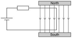
Question: Which parts of the wire experience a force, and in which directions?
Solution: The motor effect acts on currents perpendicular to the field. The top and bottom segments of the wire are perpendicular to the field lines, so they experience a force. The right-hand segment is parallel to the field lines, so it experiences no force. Using Fleming's left-hand rule (Current right at top, left at bottom; Field into the page), the forces are directed as shown below:
Magnitude of the Force and the Equation
The magnitude of the force () on a straight current-carrying wire at right angles to a uniform magnetic field depends on:
- The magnetic field strength (), measured in tesla (T).
- The current (), measured in amps (A).
- The length of the wire () within the magnetic field, measured in metres (m).
The relationship is given by the formula:
From this, we define the tesla (T). Rearranging for :
This shows that magnetic field strength is the force per unit current-length. One tesla is the field strength that exerts a force of on a wire of length carrying a current of at right angles to the field. Thus, .
Worked Example: Calculations with
Complete the following table for a wire perpendicular to a uniform field:
| /N | /T | /A | /m |
|---|---|---|---|
| (a) | 0.20 | 4.0 | 0.050 |
| 0.10 | 0.40 | (b) | 0.20 |
| 0.050 | 0.10 | 20 | (c) |
| 0.50 | (d) | 10 | 0.050 |
Solutions: (a) (b) (c) (d)
Investigating the Force Experimentally
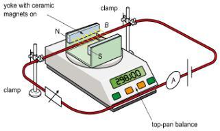
The motor effect can be investigated using a top-pan balance. When a current flows through a wire held between magnets on a balance, the upward motor effect force on the wire results in an equal downward force on the magnets (Newton's third law). This increases the balance reading. The force can be calculated using .
The Direct Current (dc) Motor
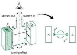
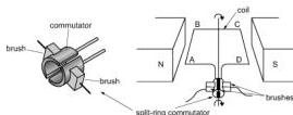
A dc motor uses the motor effect to create a turning effect (moment) on a rectangular coil. On opposite sides of the coil, the current flows in opposite directions. Since both sides are in the same magnetic field, the forces act in opposite directions, creating a couple.
Turning Effect and Rotation
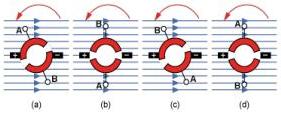
The turning effect changes as the coil rotates. It is maximum when the coil is in the plane of the magnetic field (forces are furthest apart) and zero when the coil is perpendicular to the field (forces are in the same vertical plane).
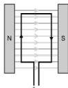
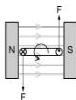
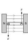
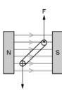
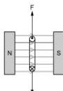
If the coil moves past the vertical without a change in current, the force direction would cause it to return to the vertical. To ensure continuous rotation, the current must be reversed every half-turn.
The Split-Ring Commutator
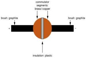
A split-ring commutator acts as a rotating switch. It rotates with the coil and is connected to the dc supply by stationary graphite brushes. Every half-rotation, the commutator reverses the connections to the coil, reversing the current direction and ensuring the forces always provide a turning effect in the same direction.
Factors that increase the turning effect in a dc motor include:
- Increasing the current (by increasing voltage).
- Increasing the area of the coil.
- Increasing the magnetic field strength (using stronger magnets or a soft iron core).
- Increasing the number of turns on the coil.
Electromagnets and Their Applications
An electromagnet consists of insulated wire wound around a soft iron core. When current flows, it behaves like a bar magnet.
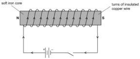
Electromagnets are advantageous because they can be switched on or off, their strength can be varied by changing the current, and their polarity can be reversed.
Applications
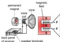
- Loudspeakers: A voice coil in a radial magnetic field moves a cone back and forth as the current varies, creating sound waves.
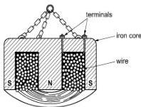
- Lifting Magnets: Used to move heavy magnetic objects like cars. Switching the current off allows for easy release of the load.
Key takeaways
- The motor effect force is always perpendicular to both the magnetic field lines and the current direction.
- Fleming's left-hand rule identifies the directions: Field (First finger), Current (Second finger), and Force (Thumb).
- Force magnitude is calculated by only when the wire and field are at 90 degrees; if parallel, force is zero.
- A split-ring commutator is essential in a dc motor to reverse the current every half-turn, maintaining continuous rotation.
In the ESAT, you might be asked about particles like electrons. Remember that the 'current' in Fleming's Left-Hand Rule is conventional current (positive to negative). Therefore, if an electron is moving to the right, the current is technically to the left.
Do not confuse Fleming's Left-Hand Rule (Motors) with the Right-Hand Rule (Generators). For the motor effect, always use your left hand. Also, ensure your units for are in metres, not centimetres, before using .
The motor effect is an application of the interaction of magnetic fields. By winding the coil around a soft iron core, the magnetic field is intensified because the core becomes magnetised and 'concentrates' the magnetic flux, leading to a much larger force for the same current.
Frequently asked questions
Why is the turning effect of a dc motor zero when the coil is vertical?
When the coil is vertical (perpendicular to the field lines), the forces acting on the two sides of the coil are in the same vertical plane. Since there is no perpendicular distance between the lines of action of these forces, the moment (or turning effect) is zero.
What happens if you reverse both the battery connections and the magnetic poles in a dc motor?
The motor will continue to spin in the same direction. Reversing one factor reverses the force, but reversing both factors results in two reversals, which cancels out the change in direction.
Why are brushes in a dc motor often made of graphite?
Graphite is a good electrical conductor and is naturally slippery (low friction). This allows it to maintain electrical contact with the rotating commutator while minimising mechanical wear.